2007年12月25日 星期二
2007年12月18日 星期二
語音辨識技術
http://ace136.auto.fcu.edu.tw/~cslin/scteach/scteach88/Tidsp/n5.htm
http://www.ascc.sinica.edu.tw/nl/87/1407/04.txt
機器辨識技術的對象,主要有聲音和影像兩大類。影像辨識所涵蓋的範圍較廣,諸如文字辨識、指紋辨識、簽名辨識、臉孔辨識、瞳孔辨識、包括上面提到的偽鈔辨識都是。聲音辨識則包括人類發出的語音、樂器發出的音樂、機器發出的噪音、動物的叫聲、聲納、大自然的聲音都是。簡單的說,就是以機器進行人類「眼睛」和 「耳朵」等兩個器官的功能「視覺」及「聽覺」,來達到自動化的效果。順帶一提的是,以機器進行「嗅覺」(人工鼻)、「觸覺」和「味覺」,雖非機器辨識技術的主流,也各有研究進行中。
何謂語音辨識
語音辨識(Speech Recognition)最主要的目的是希望電腦聽懂人類說話的聲音,進而命令電腦執行相對應的工作。當聲音藉由類比到數位的轉換裝置輸入電腦內部,並以數值方式儲存後,語音辨識程式便開始已事先儲存好的聲音樣本與輸入的測試聲音樣本進行比對工作。比對完成後點腦集輸入一個它認為最“像”的聲音樣本序號,我們就可以知道使用者剛剛唸進去的聲音代表何意,進而命令電腦做事。
設計一個語音辨識程式,至少又有兩方面的知識:
1.瞭解如何把外界的聲音訊號抓到電腦內部處理
2.瞭解聲音比對原理
語音辨識之技術分類
在「辨識技術」這個領域,依辨識對象的變化程度,而有不同的困難度。
語音特性的變化因素包括
(1)不同語者的變化:聲帶特徵、說話方式、連音耦合效應、口音等;
(2) 同一語者的變化:情緒、壓力、感冒、Lombard 效應;
(3)噪聲:汽車噪聲、空調噪聲、電話鈴聲、印表機噪聲、多人同時講話等;
(4)環境變化:反射(Re flection)、回音(Reverberation)、麥克風特性及與語者的距離等。
一般把語音辨識技術,根據詞彙大小、系統訓練、及發音方式做不同組合的分類。
詞彙大小分為
小字彙(小於 100 詞)、
中字彙(100 - 1000 詞)、
大字彙(1001 - 10000 詞)、
極大字彙(大於10000 詞)等。
系統訓練則有
(1)特定語者(Speaker-Dependent):使用前需訓練數十分鐘至數小時;
(2) 非特定語者(Speaker-Independent):不需訓練,可立即使用;
(3)系統調適(Speaker-Adaptation):數分鐘至數十分鐘的調適訓練。
至於發音方式有
(1)單字音:字與字需斷開;
(2)單詞連續發音:又細分為孤立詞、及詞詞斷開,連接成句兩種;
(3)整句連續語音: 又細分為關鍵詞萃取(Keyword Spotting)及全句辨識等兩種。
實際應用:語音辨識的作法
聽寫機(Dictation Machine)和語音指令&控制(Voice Command/Control)。
市面上的聽寫機一般為特定語者、單字音或單詞、極大字彙的語音辨識技術。
音指令&控制則為特定語者或非特定語者、單詞、中或小字彙的技術。
電腦採用數位化的語音取樣資料,我們要知道對電腦而言,即使同一個人在同一個環境使用同樣的麥克風連續發出兩次同樣的語音,語音取樣資料也不可能完全相同,因此如何把語音做正確的歸類 ,異中求同,就是問題所在。一般常見的作法是(事先或現場)蒐集足夠的語音樣本,經過抽取適當的語音特徵(Feature Extration)之後,透過訓練程序(Training Procedure),建立參考聲學模型( Acoustic Model)所需的參數。而在使用者辨識的階段,將輸入的語音樣本抽取語音特徵之後,和辨識字彙中的參考聲學模型比對,找出最接近的字彙,是為辨識結果。看似簡單,其實各步驟均有許多變化,尤其是聲學模型比對步驟的兩大問題:時序校準( Time Alignment)及參數模型比對。時序校準在於找出正確的聲學單位(如詞、音節、次音節、聲韻母、音素等)的起點跟終點,在連續音的情況下問題更為嚴重;這也是為什麼單字音比連音詞容易辨識,而連音詞又比整句連續語音容易辨識的主要原因。參數模型比對則在以什麼參數、多少參數建構參考模型,可以是語音原始樣本,也可以是語音特徵樣本,但更多的是離散(discrete )或連續密度的(continuous density)機率分佈模型。
聲學模型作法可大致分為下列幾種:實用化語音辨識技術的考慮
(1)語音模版(Template)法–適用於小字彙、特定語者的應用;
(2)動態時間校準(Dynamic Time Warping;
(3)隱馬可夫模型 (HMM,Hidden Markov Model):又可細分為利用向量量化(Vector Quantization) 技巧的離散的、
連續密度的、半連續的 (semi-continuous) 隱馬可夫模型及簡化的分段機率模型(SPM, Segmental Probabilistic Model);
(4)人工神經網路(Neural Networks);
(5)聲學知識模型;
(6)混合式(Hybrid) 作法等等。
除了小字彙的應用之外,不論在實驗室雛型或商用產品,語音辨識系統大多採用隱馬可夫模型或其變型。
在選擇語音辨識技術或產品的必須考慮的因素有下列幾點:
(1) 技術分類合適性: 詞彙大小、特定語者/非特定語者/系統調適、發音方式(單字/孤立詞/詞詞斷開/關鍵詞萃取/全句辨識);
(2) 辨識率;(3) 辨識速度;(4) 使用平台 (Platform) : 操作系統、CPU、Memory、音效卡/DSP卡、麥克風(種類與距離);
(5)成本;
(6)抗噪音能力;
(7) 是否透過電話線;
(8) 拒認能力: 提高可靠度,寧願拒認,不要錯認;
(9) 多國語言;
(10) 標準應用程式介面 (API):易於開發應用程式。
語音辨識技術之應用
TMA Associates市調公司在最近的一份調查報告中,把語音辨識產品分為四大類:
(1)電腦產品:麥克風直接連接電腦,可以電腦螢幕顯示回饋辨識結果,由於電腦使用者常為固定而長時間使用,可採用特定語者或語者調適技術;
  應用舉例如語音聽寫、PC語音控制、語音資料存取、遊戲軟體、語言訓練等;
(2)電話產品:語音透過有線或無線傳輸給辨識器,以聲音回饋給使用者,非特定麥克風,經常為短暫交談互動,宜採用非特定語者技術;
  應用舉例如電話網路之語音撥號或其他辨識/驗證服務、以語音而非按鍵控制之互動語音回應系統、PC上之電話語音辨識;
(3)消費性電子產品:麥克風為產品之一部分,小或無螢幕顯示,小包裝,常為電池供電,中低價位;
  應用舉例如電話機內建的語音撥號、可攜式電子記事簿、電視遙控、語音撥號行動電話、聲控玩具、語言學習;
(4)汽車及工業應用產品:高噪聲環境,眼及雙手忙碌,特殊裝備需求,應用免手持麥克風;
  應用舉例如汽車導覽系統、收音機控制工業品管、包裝處理、車用行動電話等。
2007年12月14日 星期五
[轉載] GPS start-up
GPS開機定位分為冷啟動、溫啟動和熱啟動三種:
冷啟動:以下幾種情況開機均屬冷啟動。
初次使用時;電池耗盡導致星曆訊息丟失時;關機狀態下將接收機移動1000公里以上距離。
溫啟動:距離上次定位的時間超過兩個小時的啟動。
熱啟動:距離上次定位的時間小於兩個小時的啟動。
有時候如果機器有軟件問題,需要進行冷啟動,冷啟動可以使用gpsviewer進行。
2007年12月6日 星期四
BattDrv_saving power issue
當usb發生中斷將電池狀態通知ce
int WINAPI CheckACChargerThread()
{
SYSTEM_POWER_STATUS_EX2 tmpst;
PBATTERY_CONTEXT pbc = (PBATTERY_CONTEXT) &gBatteryContext;
RETAILMSG(1, (TEXT("++CheckACChargerThread \r\n")));
while(TRUE)
{
InterruptDone(SYSINTR_ACChargerDetect);
WaitForSingleObject(g_hACChargerDetect, INFINITE);
//////////////////////////////////////
// update battery status information
LockBattery();
BatteryAPIGetSystemPowerStatusEx2(&tmpst, sizeof(tmpst), TRUE);
UnlockBattery();
// has anything changed?
if(memcmp(&tmpst, &pbc->st, sizeof(pbc->st)) != 0)
{
// yes, update our global variable and notify the power manager
pbc->st = tmpst;
PowerPolicyNotify(PPN_POWERCHANGE, 0);
}
//////////////////////////////////////
if(PIO_READ_INPUT(GPIO, GPIO_GROUP(0),GPIO_INDEX(2)))
{
RETAILMSG(1,(TEXT("++CheckACChargerThread USB IN!!!\r\n")));
}
else
{
RETAILMSG(1,(TEXT("++CheckACChargerThread USB OUT!!!\r\n")));
}
}
}
2007年10月16日 星期二
把code從public移到flatform
以mainstoneⅢ LCD driver為例子
Ariel把在
WINCE500\PUBLIC\csp_pxa27x\oak\pxa27x下的xllp folder搬至WINCE500\PLATFORM\MC55\src下
- dirs內需將xllp加入

WINCE500\PUBLIC\csp_pxa27x\oak\pxa27x下的display folder搬至WINCE500\PLATFORM\MC55\src\drivers下
- dirs內需將display加入

接著修改WINCE500\PLATFORM\MC55下的sources.cmm
這樣才能找的到include的檔案

大至上只需要一些些小步驟要注意,這樣就不會出現complier過不了了。
2007年10月15日 星期一
SD QC搬移需注意的地方
在XBOOT\Boards\TANJAY內自己新建立DRIVERS folder需要注意幾點:
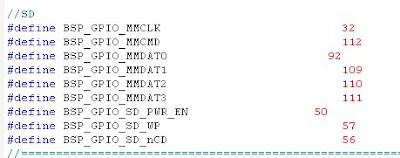
基本上的一些般移動作就不多加說明,重要的是一些makefile要多加注意,以下是Ariel有遇過的問題還有覺得較需注意的地方,可以參考看看
- XBOOT\Boards\TANJAY\DRIVERS\Makefile要修改
- XBOOT\Make\tanjay.cfg要修改
- XBOOT\Boards\TANJAY\platform.c內clock要注意是否有設好
- XBOOT\Boards\TANJAY\H\bspgpio.h要注意GPIO是不是符合電路圖
2007年9月17日 星期一
MDD與PDD
以Audio driver舉例:
若我們要implement一個stream interface driver,我們可以使用Microsoft提供的MDD(model device driver) library, Wavemdd.lib, 透過audio device driver service-provider interface(DDSI) function來實現stream interface function.
使用Wavemdd.lib,那我們就要create 一個對應的PDD(platform-dependent driver) library來implement audio DDSI function.
PDD library 通常會被稱為Wavepdd.lib,僅管它可能是不需要的, 但這兩個library會從audio driver被link起來 成為一個.dll的檔案,Wavedev.dll。
如圖所示:

2007年8月30日 星期四
I2C Bus
- I2C 為 Inter-Integrated Circuit的縮寫,I2C Bus顧名思義就是IC之間溝通的匯流排
- I2C Bus為飛利浦(Philips)在1980年代所發展的雙向二線式的串列匯流排(Serial Bus)標準
- 資料線:Serial data line (SDA)
- 時脈線:Serial clock line (SCL)
- I2C Unit允許Processor透過I2C Bus來服務master和slave 裝置
- 資料在I2C Bus上可以用三種速度被傳送
- Standard-mode: 100 kbit/s
- Fast-mode: 400 kbit/s
- High-speed mode: 3.4 Mbit/s
- 相較傳統平行匯流排(Parallel Bus)
- 架構簡單,只需要二條線就能傳送資料,可靠度及安全性佳
- 省去平行匯流排所須的解碼電路
- 降低平行匯流排可能因接線太多而造成的電磁干擾和靜電放電的副作用
- 系統包含μC及其他周邊
- 希望將連接的成本降至最低
- 系統不需要很快的傳輸速度
- 希望應用於Multi-Master系統
- I2C Bus介面本身為Open Drain或是Open Collector構造,因此應用時需外加電源及提升電阻才能運作

- I2C Bus定義一個由序列資料/位址線(SDA) 和序列時脈線(SCL)組成的序列協定給I2C Bus上的處理器來處理通過的資訊
- I2C Bus上的每個裝置是由一個獨特的7bits address來識別而且可以在master或slave模式下當成傳送端或接收端來操作

- for example

- 當Processor 在I2C Bus上作用為master時,它定址一個EEPROM為slave來接收資料。當Processor定址EEPROM時,它是一個master傳送端而EEPROM是一個slave接收端。當Processor讀取資料時,它是一個master接收端而EEPROM是一個slave傳送端。不管它是傳送端或是接收端,master會產生時脈信號,起始傳送,還有終止傳送。
- I2C Bus是一種同步傳輸協定,其資料傳送形態包含
- 開始(Start)
- 位址(Address)
- 讀/寫(R/nW)
- 資料(Data)
- 確認(Acknowledge)
- 停止(Stop)

- SDA若要變化,只有在SCL為低電位時才可以改變,而SCL在高電位時,其對應同時SDA的狀態(高電位或低電位)就是其傳送的位元(1 or 0)
- 開始(Start)
- Master必須送出”start”信號才能取得I2C Bus的控制權
- 當I2C Bus沒有動作時,SCL和SDA都保持在高電位
- I2C Bus動作時,master先在SDA送出低電位,經過一小段時間後,再將SCL變成低電位

- 停止(Stop)
- 和”start”信號的動作相反
- Master完成和slave的動作後,先將SCL釋放至高電位,經一小段時間在將SDA放至高電位

- 位址(Address)
- 每一個送到Bus上的資料都必須是8bit
- 以standard mode為例,Address有7個bit,master會先傳送MSB到Bus上,再依次傳出其他bit
- 讀/寫(R/nW)
- 緊接著Address,只佔一個bit 為LSB,高電位時為Read,低電位時為Write

- 確認(Acknowledge)
- Slave正確地收到資料後,會發出”ACK”信號向master表示收到
- Master會將SDA釋放成高電位,slave確認時會將SDA拉至低電位
- Slave未能正確地收到資料,slave則不動作,SDA會維持在高電位

- 資料(Data)
- 和Address及R/nW一樣,只不過資料可能由master或slave送出,由master或slave接收,而Address及R/nW則是由master送出,slave接收
- 資料的意義隨著裝置的不同而不同

- 簡單的溝通原理
- Uc要對memory寫入資料
- Uc發出start訊號告訴其他device它要動作了,接著發出”device address”(每個deivce都有一個唯一的address)和讀寫訊號
- Memory收到uc要它做讀寫動作,便發出ack告訴uc我收到了
- 然後uc傳送欲寫入的address(這裡是指memory address)給memroy
- Memory再發出ack給uc
- Uc再將欲寫入的資料送給memory
- 寫入完畢後,memroy又發出ack給uc
- 接著uc送出stop告訴bus上的所有device我的事做完了

- Master接收Slave傳送 / 重複START / Master傳送Slave接收

- Single-Master: 只有一個μC發號施令,主控整個系統
- Multi-Master: 系統有二個以上的μC發號施令,其他的μC(slave)只能受主控的μC (master)控制,在不對外界送出命令時,master本身又可以變成slave

- 就是說有兩個以上的μC時,只有一個主控的master μc,其他的μc均當成slave
- Multi-master就只靠scl和sda這兩條線來完成,在兩條線上有很多個master傳送資料,那不是很容易發生衝突嗎? 靠著open collector (drain)的特性,scl和sda均可作wired_and動作,這些問題都可以解決。達成arbitration 和 synchronization的功能以確保bus正常運作。
- Multi-master功能需要I2C Bus arbitration(調停),當二或多個master在最短的停留時間產生START信號時調停將發生
- 使用wired-AND硬體線路,因此多個master發出同樣狀態的信號,傳輸不會遺失資料
- 假如包含的address和R/nW或是data不一樣時,master會發出高電位狀態來表示調停失敗並關閉它的SDA,然後回到slave模式
- 當兩個以上的master送出不同的位址時,低位址會擁有優先權
- 每個I2C Bus上的master為了在SCL上的資料傳輸會產生它自己的時脈
- 不同頻率的時脈連接到SCL,當時脈是在高電位期間時資料是有效的
- Master擁有最長的時脈週期者會將SCL維持在低電位
- 當兩個master發出的信號頻率不同時,SCL的頻率會以最低的為標準
- Service an internal interrupt
- If a slave can’treceive or transmit another complete byte of data until ithas performed some other function, for example servicing an internal interrupt, it can hold the clock line SCL LOW to force the master into a wait state. Data transfer then continues when the slave is ready for another byte of data and releases clock line SCL.
- Handshake
- The clock synchronization mechanism can be used to enable receivers to cope with fast data transfers, on either a byte level or a bit level. On the byte level, a device may be able to receive bytes of data at a fast rate, but needs more time to store a received byte or prepare another byte to be transmitted. Slaves can then hold the SCL line LOW after reception and acknowledgment of a byte to force the master into a wait state until the slave is ready for the next byte transfer in a type of handshake procedure.

2007年7月20日 星期五
How to load a driver into user mode
要如何將driver load 到 user mode?
其實很簡單
只需要設定platform.reg中Flags的value為 DEVFLAGS_LOAD_AS_USERPROC(0x10)
以上次建出來的Driver為範例。
platform.reg
//===============================
[HKEY_LOCAL_MACHINE\Drivers\BuiltIn\Cin]
"Dll" = "CIN.dll"
"Prefix" ="CIN"
"Index"= dword:1
"Order"= dword:0
"FriendlyName" = "CIN Demo Driver"
"Ioctl" = dword:0
"Flags" = dword:10
; Flags==0x10 is DEVFLAGS_LOAD_AS_USERPROC
//===============================
platform.bib
//===============================
CIN.dll $(_FLATRELEASEDIR)\CIN.dll NK SH
//===============================
run 出來的結果

千萬要注意哦
bib檔的SHK要改成SH哦,沒改的話會出現錯誤。
run出來的結果

How to create a CE 6.0 driver
1.首先在BSP底下建你要的driver folder。
\WINCE600\PLATFORM\DEVICEEMULATOR\SRC\DRIVERS

2.接著建立所需的makefile、.def、sources、.c(or .cpp)檔。 內容設定如下:簡略說明,可參閱stream driver文章。
D:\WINCE600\PLATFORM\DEVICEEMULATOR\SRC\DRIVERS\CINTEST

.def檔
//=========================================
LIBRARY CINTEST // driver folder 名稱
EXPORTS
// 要export 的function
XXX_Init
XXX_Deinit
XXX_Open
XXX_Close
XXX_IOControl
XXX_PowerUp
XXX_PowerDown
XXX_Read
XXX_Write
XXX_Seek
//=========================================

source檔
//=========================================
SYNCHRONIZE_DRAIN=1
TARGETNAME=CIN //.dll的名稱
RELEASETYPE=PLATFORM
TARGETTYPE=DYNLINK
TARGETLIBS= \
$(_SYSGENSDKROOT)\lib\$(_CPUINDPATH)\coredll.lib \ //會呼叫到的library
SOURCES= \
cin.c \\用到的.c檔
//=========================================

3.修改platform.reg和platform.bib檔
\WINCE600\PLATFORM\DEVICEEMULATOR\FILES
platform.reg
//=========================================
[HKEY_LOCAL_MACHINE\Drivers\BuiltIn\Cin]
"Dll" = "CIN.dll"
"Prefix" ="CIN"
"Index"= dword:1
"Order"= dword:0
"FriendlyName" = "CIN Demo Driver"
"Ioctl" = dword:0
//=========================================

platform.bib
//=========================================
CIN.dll $(_FLATRELEASEDIR)\CIN.dll NK SHK
//=========================================

2007年7月13日 星期五
system calls
簡言之就是應用程式與作業系統的介面
2007年7月4日 星期三
User Mode Driver Framework
- allows an intermediate driver to load in user mode
- cannot directly access hardware
- some drivers will be more stable in user mode
- reflector in kernel makes a user mode driver work as if it was a kernel mode driver

- the user mode driver reflector, which reside inside the device manager.
- manages the user mode driver host processor.
- forwards the requests that are issued by the device manager.
- provides services for a user mode driver.
- the user mode driver host, which is a user mode application that is launched and managed bye the user mode driver reflector.
- it is used at the kernel's request to launch and to manage a user mode driver.
- it is responsible for mounting the API of a volume in order to receive forwarded requests from the user mode driver reflector.
- stores configuration information for applications, drivers, and the OS.
- OS uses registry to locate and load device drivers.
- Same basic setup as the desktop windows OS registry.
- space is limited, so keep any new entries short.
- manages devices and their interfaces.
- decides which drivers to load.
- uses registry to find drivers.
- runs continuously.
Kernel Mode Drviers VS. User Mode Drivers
Prior to CE6, device drivers primarily resided in the device.exe process.
The new kernel architecture provides more flexibility by providing two different driver models. The old device.exe functionality has been moved into the kernel, and a new user device process (udevice.exe) has been introduced. This change results in two different driver models, kernel mode drivers and user mode drivers. BSP developers must choose how each of their drivers will be implemented on a particular platform.
Kernel Mode Drivers
Kernel mode drivers are loaded by device.dll inside of the kernel. This is the default behavior, and most closely resembles the old device.exe model. The big win here is performance – the expensive interprocess calls (thunks) have been eliminated. There is no need for the user mode process initiating a driver access to be switched out, because the user mode process coexists with the kernel. The kernel includes the file system and device drivers so everything is resident in memory at the same time.
This new performance benefit comes at a price. Kernel mode drivers are now a part of the kernel, and they have full privileges for the entire kernel address space. A driver failure that results in memory corruption could easily bring down the kernel and with it the entire system. Therefore it’s critical that kernel mode drivers be robust.
User Mode Drivers
Microsoft has designed the user mode driver model to have a very high level of compatibility with kernel mode drivers. There are very few differences between the two models, and a driver written for user mode can be loaded into kernel mode with no changes. A new kernel component called the user mode driver reflector handles the interface between user mode applications and the user mode driver. This means that applications do not need to be aware of how a particular driver was loaded.
It’s a simple matter to load a driver into user mode instead of the default kernel mode. There is a new bit defined in the Flags registry key that if set tells the kernel to load the corresponding driver into user mode. That’s it – nothing more to it. The user mode driver will run in its own process isolated from the kernel and the rest of the system. If the driver fails for some reason only its copy of udevice.exe is affected, the rest of the system should remain intact.
BSP developers now have the option of choosing between a high performance kernel mode driver and a more protected user mode driver. Untrusted third party drivers can be loaded into user mode to increase system security and robustness. Unstable or otherwise questionable drivers can start life in user mode and then be moved to kernel mode as they become proven.
參考來源:http://www.bsquare.com/blog/default-aug_21.asp
2007年6月20日 星期三
MDOC Read
//output、input record for Bindary partition
flOutputStatusRecord outputStatusRecord;
flBDKOperationInput bdkOperationInput;
//output、input record for Disk partition
flReadWriteInputFH readWriteInput;
flReadWriteOutput readWriteOutput;
flMountInputFH mountInput;
flOutputStatusRecord outputStatusRecord;
DWORD bytesReturned;
//open DOC driver
hDoc = CreateFile(L"DSK6:",GENERIC_READ|GENERIC_WRITE,FILE_SHARE_READ|FILE_SHARE_WRITE,
NULL, OPEN_EXISTING, 0, 0);
if (INVALID_HANDLE_VALUE == hDoc)
{
return 0;
}
//Read Bindary partition=================================
// Initialize for BDK read
bdkOperationInput.type = BDK_INIT_READ;
bdkOperationInput.partitionNumber = 1;
bdkOperationInput.bdkStruct.startingBlock = UnitNumber;
bdkOperationInput.bdkStruct.length = kDocBlockSize;
bdkOperationInput.bdkStruct.oldSign[0] = 'B';
bdkOperationInput.bdkStruct.oldSign[1] = 'I';
bdkOperationInput.bdkStruct.oldSign[2] = 'P';
bdkOperationInput.bdkStruct.oldSign[3] = 'O';
bdkOperationInput.bdkStruct.signOffset = 8;
if (!DeviceIoControl(hDoc, FL_IOCTL_BDK_OPERATION, &bdkOperationInput, sizeof(bdkOperationInput), &outputStatusRecord, sizeof(outputStatusRecord), &bytesReturned, NULL))
{
return 0;
}
//Read BDK blocks
bdkOperationInput.type = BDK_READ;
bdkOperationInput.partitionNumber = 1;
bdkOperationInput.bdkStruct.length = kDocBlockSize;
bdkOperationInput.bdkStruct.bdkBuffer = gBuffer;
if (!DeviceIoControl(hDoc, FL_IOCTL_BDK_OPERATION, &bdkOperationInput, sizeof(bdkOperationInput), &outputStatusRecord, sizeof(outputStatusRecord), &bytesReturned, NULL))
{
return 0;
}
//==============================================================
//Read Disk partition==========================================
// calling for FL_IOCTL_MOUNT_VOLUME_FH/FL_MOUNT
mountInput.partitionNumber = 0x2; //BDTL2
mountInput.type = FL_MOUNT;
if (!DeviceIoControl(hDoc, FL_IOCTL_MOUNT_VOLUME_FH,&mountInput,sizeof(mountInput),&outputStatusRecord,sizeof(outputStatusRecord), &bytesReturned, NULL))
{
return 0;
}
// calling for FL_IOCTL_WRITE_SECTORS_FH
readWriteInput.partitionNumber = 0x2; //BDTL2
readWriteInput.firstSector = 0;
readWriteInput.numberOfSectors = SectorNumber;
readWriteInput.buf = gBuffer;
if (!DeviceIoControl(hDoc, FL_IOCTL_READ_SECTORS_FH, &readWriteInput, sizeof(readWriteInput), &readWriteOutput, sizeof(readWriteOutput), &bytesReturned, NULL))
{
return 0;
}
//calling for FL_IOCTL_MOUNT_VOLUME_FH/FL_DISMOUNT
mountInput.type = FL_DISMOUNT;
if (!DeviceIoControl(hDoc, FL_IOCTL_MOUNT_VOLUME_FH,&mountInput,sizeof(mountInput),&outputStatusRecord,sizeof(outputStatusRecord), &bytesReturned, NULL))
{
return 0;
}
//===================================================================
//close Doc handle
if(hDoc)
{
CloseHandle(hDoc);
}
2007年6月1日 星期五
sort
int a[7]; //input sequence
void main()
{
Quicksort(0,6);
}
Quicksort(int f, int l)
{
if f>=l then
{
return;
}
int X = a[f];
int i = f;
int j = l;
while i < j do
{
while a[j] >= X do
{
j = j-1;
}
a[i] = a[j];
while a[i] <= X do
{
i = i+1;
}
a[i] = a[j];
}
Quicksort(f, j-1);
Quicksort(j+1, l);
}
//============================
2.Straight_selection_sort
int a[7]; //input sequence
void main()
{
straight_selection_sort();
}
straight_selection_sort()
{
int i, j;
int x;
for( i = 0 ; i < 6 ; i ++)
{
for( j = i+1 ; j < 7 ; j++)
{
if( a[i] > a[j] )
{
x = a[i];
a[i] = a[j];
a[j] = x;
}
}
}
}
2007年5月24日 星期四
How to use Interrupt
create IRQ(hardware interrupt)
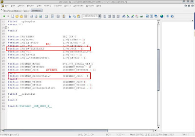
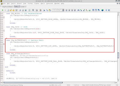
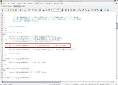
3.SYSINTR and IRQ mapping
VOID OALIntrStaticTranslate(
  UINT32 sysIntr,
  UINT32 irq
);
4.create Event
- ensure the event are created successfully.
- InterruptInitialize(), this function initializes a hardware interrupt with kernel, and allows the device driver to register an event and enable the interrupt. check it has created successfully.
- create a thread and ensure it has created successfully
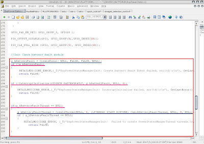
5.wait event occur
- InterruptDone(), this function signals to the kernel that interrupt processing has been completed.
- WaitForSingleObject(), this function checks the current state of the specified object. If the object's state is nonsignaled, the calling thread enters a wait state.
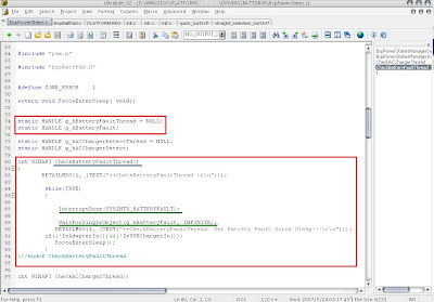
2007年5月16日 星期三
MPLAB與ICD2連結的操作
1先將ICD2與電腦連接
2再將ICD2與Target Board連接
3電源由Target Board供應
拔除:建議直接將ICD2與Target Board連接拔除
【軟體操作】
(燒錄後由電腦可以控制)
path:Debugger→Select Tool→MPLAB ICD2
步驟如下圖所示
1.Reset and connect to ICD2,確認ICD2有連接
2.Program target device,將code燒錄至IC中
3.Reset
4.Run(若有中斷點需要全部清除)

(燒錄後可以不需與電腦連接)
path:Programmer→Select programmerl→MPLAB ICD2
步驟如下圖所示
1.Reset and connect to ICD2,確認ICD2有連接
2.Program target device,將code燒錄至IC中
3.只需電源供應給Target Board即可

2007年4月27日 星期五
如何在WINCE Build "Pubilc" folder
2007年4月26日 星期四
在UltraEdit編輯環境下使用Hi-TechC
可以到http://www.htsoft.com下載它的demo板。
在MPLAB環境下可以直接使用Hi-Tech進行編譯。
但是在MPLAB環境下使用有很多的不便,比如不能進行中文注釋,關鍵字不能彩色顯示等。
一 般設計者都喜歡在Ultra Edit編輯環境下進行編寫和修改,在MPLAB環境下編譯模擬,要來回切換,非常的不方便。還有,因為MPLAB沒有感知功能,在Ultra Edit修改以後,MPLAB並不知曉,所以還要重新打開這個檔才行。如果在Ultra Edit環境下也能編譯就好了!
下列說明怎樣設置和使用。
第一步: 打開Ultra Edit編輯器,選擇功能表“Advanced”的“Tool Configuration”,點擊打開Tool Configuration Window,如圖1所示。
在“Command Line”透過“Browse”找到你安裝的PICC的路徑,如 C:\HT-PIC\bin\picc.exe, 空格,然後再輸入:“-16F877 -Zg –O –E %F”(不要輸入引號)。
簡單解釋一下:
-16F877是利用PIC16F877的資源,因為PIC16F877比較多,這樣就可以編譯其他的PIC系列的單晶片微控制器了;
-O –Zg都是代碼優化命令;
-E是產生錯誤檔的命令,有了這個命令當產生錯誤以後,我們點擊錯誤提示,游標就會停留在存在錯誤的語句行上,這樣就非常方便我們修改錯誤;
%F是編譯當前文件的命令。
當然我們也可以加其他的命令,請查閱有關Ultra Edit的Help。
第二步:在Working Directory輸入:“%P” (不要輸入引號)。
意思是把編譯生成的文件放到當前檔案的路徑下。如圖1所示。
第三步:在“Menu Item Name”輸入你取的名字,如輸入的是:“PICC”。如圖1所示。
第四步:為了看到輸出結果我們還要做下面的設置,在“Save Active File”前面的方框裡打勾;
在“Output to List Box” 前面的方框裡打勾;在“Capture Output” 前面的方框裡打勾。如圖1所示。
最後點擊“Insert”。設計好的情形如圖1所示。不要忘了還要點擊“OK”,不然前面的工作就白做了。
好了,你現在點擊Advanced功能表,就會在看到“PICC”選項了!
趕緊打開一個PIC的.C檔試試成果吧!點擊“Advanced”功能表下的PICC選項,編譯結果馬上出現在我們的面前!
效果如圖2所示,在.C檔所在的路徑下還生成了hex等檔案。
如果出現錯誤,在輸出視窗會有提示的。如果出現錯誤,在輸出視窗會有提示的。
點擊錯誤提示,提示符就會跳到出錯行。效果如圖3所示。
不過建議不要直接把hex檔下載到單晶片微控制器,應該用MPLAB編譯、模擬後,覺得沒有什麼問題再下載到單晶片微控制器進行測試。

圖1

圖2

圖3
參考出處:http://pdf.18ic.com/post_14_505_1.html
2007年4月23日 星期一
LED issue_661
USB cable插在661上充飽電時(LED亮綠燈),當按Power Key進suspend,LED會亮紅燈,這是因為進入suspend,GPIO會設為 output high。
請參閱\WINCE500\PLATFORM\MGPS\KERNEL\OAL\sleep.c
DWORD g_dwRomGpioConfig [][3] = {
{ 0xCFFFFFFF, 0x0FBFFFD0, 0xC
{ 0x
{ 0xFFF7FFFF, 0xFFF7FFFF, 0x00000000 },
{ 0xFFFFFFFF, 0xFE0FFBF0, 0xC
{ 0x7FFFFFFF, 0x7FFF1D
{ 0xFFDFFFFF, 0x
};
{ 0xCFFFFFFF, 0x0FBFFFD0, 0xC
{ 0x
{ 0xFFF7FFFF, 0xFFF7FFFF, 0x00000000 },
{ 0xFFFFFFFF, 0xFE0FFBF0, 0xC
{ 0x7FFFFFFF, 0x7FFF1D
{ 0xFFDFFFFF, 0x5277FFFF, 0xADA80200 },//p9 output low,p23 output low CHAR_DONE output high
};
陣子才會變綠燈 , 當初為了這一個 Bug 所以 battery driver 當初改成如果電壓在 4.17V 以下就把
CHAR_DONE 拉 HIGH 變紅燈 , 在 4.17V 以上就把他拉 LOW 變綠燈 , 但在 sleep時我們無法
掌控 CHAR_DONE , 這個 Bug 就會跑出來。
2007年4月19日 星期四
MPLAB IDE操作環境
建立Project時,路徑不可以有中文命名,因此要特別小心。
path:Project>Project Wizard
2) Setting Up Language Tools
選擇正確的assembler (MPASM assembler) 、linker for PIC MCU devices
path: Project>Set Language Tool Locations
Project> Select Language Toolsuite
3) Adding Files to the Project
- A source file has not yet been selected, so we will use an MPLAB IDE template file. The template files are simple files that can be used to start a project. They have the essential sections for any source file, and contain information that will help you write and organize your code.
- Next, add the second file for your project, the linker script. There is a linker script for each device. These files define the memory configuration and register names for the various parts.
4) Building the Project
path:Project>Build All
5)選擇build output window輸出訊息
patjProject>Build Options>Project
→MPASM Assembler tab
→Categories→Select "Output"
→Diagnostic level→Select "Errors only" or ...
6)Testing Code with the Simulator
要測試 code 時,軟體或是硬體需要去執行PIC MCU指令。
MPLAB IDE 提供三個debug tool。
Hardware tools有MPLAB ICE、MPLAB ICD 2,可以真正將 code在實際的device執行。
如果沒有device可使用,Software tool的 MPLAB SIM simulator 可以用來測試。
Path:Debugger>Select Tool
7) Processor Reset
會出現綠色箭頭show出程式開始的地方
path:Debugger>Reset>Processor Reset
2007年4月11日 星期三
MCU
也有人稱為單晶片微控制器(Single Chip Microcontroller),
它是將ROM、RAM、CPU、I/O集合在同一個晶片中,為不同的應用場合做不同組合控制。
在MCU開發方面,以架構而 言可分為兩大主流:RISC(Reduced Instruction Set Computer)與CISC(Complex Instruction Set Computer)。
RISC代表MCU的所有指令都是利用一些簡單的指令組成的,簡單的指令代表 MCU 的線路可以盡量做到最佳化,而提高執行速率,相對的使得一個指令所需的時間減到最短。
對於 RISC 來說,因為指令集的精簡,所以許多工作都必須組合簡單的指令,而針對較複雜組合的工作便需要由『編譯程式』(compiler) 來執行,而 CISC MCU因為硬體所提供的指令集較多,所以許多工作都能夠以一個或是數個指令來代替,compiler 的工作因而減少許多。
至於RISC 與 CISC 的取舍之間,似乎也是MCU硬體架構與軟體(Compiler) 的平衡之爭,應該沒有絕對優勢的一方,只能說因應不同的需求而有不同的產品
參考出處:http://www.eettaiwan.com/ART_8800076794_617717,876045.HTM.582b52dd
2007年4月9日 星期一
BattDrv_charging_661
狀態:希望當battery充電時,LED亮紅燈,飽電時,LED亮綠燈。
問題:系統Suspend時,就算是充飽電狀態,LED還是呈現紅燈。
解析:因為當Battery充電時,只要CHG_DONE或是CHG_STA其中一種狀態成立,Green LED就會導通(CHG_DONE和CHG_STA做OR後由CHG_FUL控制LED)。但當系統Suspend時,CPU呈現不動作狀態,此時的CHG_DONE的GPIO便不動作,整個Charg的動作會交給Charg IC來做。因為CHG_DONE是由軟體控制而CHG_STA則是隨著流過Charg IC的電流來決定,當流過的電流小到一個呈度(由電池曲線決定),則表示已充飽電了,但也因為如此,所以要等Charg IC充飽電則需要在過一段時間,LED才會亮起綠燈。


